The model is now complete and I have decided to donate to anyone who
has the space to display it and the throughput of visitors to justify having
it.
It could be a great crowd puller for somebody. I do not ask for any payment
to myself but would expect the recipient to make an appropriate donation to an organisation which
gives medical and other humanitarian aid to victims of disasters and conflict
worldwide. This is called The Gift of The Givers. My Krupp 288 model is also on offer on the same terms. Contact me: shepherdmeccano@gmail.com
Update - check out my 3rd model (under construction) Bucyrus Erie 4250-W (Big Muskie)
---------------------------------------------------------------------------------------------------------------------------
The story of building the Marion 6360 stripping shovel
After finishing
the Meccano Krupp 288 bucket wheel excavator model I decided to build a model
of the Marion 6360 stripping shovel in the same scale (1 in 18) also using
self-made replica parts and with the help of the same laser-cutting facility in
Port Elizabeth (Steelcut Services) to cut out the mild steel blanks. Once again
I am also indebted to Mr. Screw of Port Elizabeth for supply of all the
stainless steel fixers . A big thank you to Sally and Roxy respectively at
these companies for their knowledge, efficiency and help in procuring all the
requirements to build the model.
 |
| June 2016. Photo by Clint Bradfield of Foto First Grahamstown |
Background – stripping shovels
Stripping shovels were essentially
an American development and were built with the purpose of removing the layer
of overburden in mines (mainly coal mines).
The 1960’s saw competition between 2 companies, Bucyrus-Erie and Marion,
to build the largest ever such machine, a race eventually won by Marion, with
their mighty 6360 machine, a 21-storey high giant with a mass of 12,730 metric
tons and a bucket capacity of 132 cubic metres. A picture of the machine is shown here
Also have a look at this video :
Discovery Channel's "Mega-Excavators" revisits "The Captain," a massive stripping shovel that suffered an untimely death when it was destroyed in a fire
Principal parts of 6360
An excellent line drawing by William E Oldani, shows the principal parts diagrammatically. The business end of the machine is a single
bucket which is fixed at the end of a dipper arm. At the rear of the bucket is a door which can
be opened to dump the load on the overburden pile by pulling on a cable. (The 6360 had two doors – the only model to
have these - side by side, to lessen the shock when they slammed shut). At the
other end of the dipper arm was a pivot from which 2 arms pivoted. One such unit was roughly vertical and in
turn pivoted at the front-end of a huge machinery hall. This was called the stiff leg. The other unit was roughly horizontal and was
driven back and forth by a very powerful thrusting mechanism called the crowd
mechanism. This was the source of the
thrust action of the bucket against the work face, so powerful that the rock
almost seemed to explode when the teeth of the bucket made contact.
There were 2 types of crowd
mechanism used in the industry. One
employed a rope drive, the other a rack and pinion drive. The latter type was use on the 6360. A feature unique to the 6360 was that it had
twin toothed rack booms, and not just one.
Inspection of the drawing will also
show a main supporting boom which is fixed at 45° to the horizontal. At the top end of this boom are a set of
pulleys over which the hoist ropes ride.
This hoist mechanism is the other part of the digging story and allows
the load to be hoisted out of the mine pit and deposited at a chosen level on
the overburden pile.
On following the hoist ropes back
one can see that they run over more pulleys at the top of a gantry which
reaches nearly as high as the top of the main boom from where they go down into
the large machinery hall. There they
wind onto the hoist winding-drums. It is also evident that the tall gantry is
responsible for holding up the main boom via 12 strong steel cables. The 6360
was unique in that it had 2 gantries side by side. This double gantry also gave support to the
double crowd mechanism.
Working our way downward we see
that the entire upper part of the machine (everything described so far) can
slew through 360°on an enormous roller-race. This action is also called “swing”. The
roller-race is mounted on an extremely strong mainframe which is, in turn,
supported by 8 crawler mechanisms (grouped in pairs), one pair at each corner. These pairs can be steered by means of
tillers which are moved by hydraulic rams anchored to the mainframe.
Several systems work together to
allow the machine to move on uneven ground while maintaining maximum contact
with the ground. Firstly, each pair of
crawlers can be moved vertically by means of huge hydraulic levelling pistons
(of diameter 1.67 metres). Secondly,
each crawler is mounted on a rocker axle perpendicular to the direction of
travel, and finally, each pair of crawlers can roll on an axis parallel to the
direction of travel. This could be
called rock and roll suspension or we could say that the crawlers can rotate on
3 mutually perpendicular axes, the third axis being the vertical one involved
in steering.
Operation
One would be struck, when watching
this machine working, by the silence of the operation – except for the crash of
the bucket into the rock face and the subsequent rumble of spoil as the bucket
doors open. This is because the machine
is electrically powered. Power is
brought in through an armoured cable at 14,000 volts AC. Inside the machinery hall are 4 motor
generator units (MG units) which convert this to 220 or 440 volts DC to power
all actions. About 30,000 horse power is
the maximum power requirement (about 22 megawatts). Mounted at the front and
back of the lower mainframe are 2 large winding drums for the HT supply cable
which allow the machine to change its digging direction without turning around.
The staff complement on the 6360
was three. The digging controller sat in
an air-conditioned cabin (with kitchen and toilet ) at the left front of the
machinery hall; a ground man steered the machine remotely from the ground (he
also had a substantial bulldozer on hand to move obstacles out of the way of
the crawlers); finally, an oiler moved constantly around the machine checking
its lubrication, etc. An interesting
feature was a small 3-man elevator which ran in the hollow swing kingpin and
took staff from the lower works up to the driver’s cab or to the roof of the
machinery hall, a vertical journey of 8 floors.
Tragic end of the 6360
Only one 6360 was built. It was the largest fully mobile land-based
machine in the world when it was commissioned in 1965. (The title was taken
away when the German 240,000 cubic metre per day bucket wheel excavators were
built in the 70s.)
The 6360 had a sad end. It caught fire in 1991 when an hydraulic line
burst spraying onto electrical equipment.
Over the years a large amount of grease had built up in the swing roller
race area and this burnt fiercely for nearly a day. The crew escaped unhurt but a great deal of
damage was done as fire teams had difficulty getting equipment to the machine
due to the remote part of the mine and difficult terrain. It was deemed uneconomical to repair and was
scrapped in 1992.
My model - introduction
The model I am building (at a scale
of 1 in 18) will have a height of 12 feet and width of 5 feet. With dipper fully extended it will be about
17 feet long. Estimated mass is in excess of 1,100 kg which is not as much as my
Krupp 288 model which comes in at 1,335 kg (making it the largest Meccano model
in the world, I believe). The Marion
6360 model could possibly be the second largest. The 6360 is more compact and chunkier than
the Krupp 288. It will fit into a double
garage which has a ceiling height of 13 feet.
My model – lower works
Much of the first year of
construction on the 6360 has been taken up with drilling the parts, flatting
down burring, phosphate treating and painting.
All girders and most plates have now been done (January 2016). As with
the Krupp model, the most-used plate is the 5½" by 2½", with nearly
4000 being done in gauges 0.6, 1.0 and 2.0mm.
I still need to make about 400 in a 0.2 gauge – to be cut from used
spray paint cans - used in the machinery hall roof. The heavy gauge plates are
used mainly in the crawler system and some parts of the lower works (steering
thrusters) and key parts of the mainframe.
I view the construction of these giant models
in terms of a series of boxes, supporting one on top of the other, as in Figure
1.
 |
| Fig 1 |
In the average Meccano model built
from only genuine parts you would only find the top two boxes. This is fine if your model weighs in at, for
example 100 kg, but to go to say, 500
kg, you need the third box (1.0 mm gauge) and for something around 1000 kg, the
lowest box (2.0 mmm gauge) becomes necessary.
Having said so much about parts
manufacture I am happy to report that I have also been able to work on the
lower works of the machine. The strength
of the mainframe is provided by a toroidal frame consisting of 32 bulkheads,
10½" by 10½", with a plating of 1.0 mm plate around the
perimeter. These bulkheads have their
positions in a circle defined by thirty two 5½" by 3½" plates at the
centre in exactly the same way as the toroidal frames of the Krupp 288 were
laid out. The outer surface of the torus
is created by two layers of 5½" by 2½" (0.6 gauge) plates, overlapped
in the lateral sense. The depth of the
torus is 22 holes, with joiner flat girders keeping the two 11-hole deep curved
surfaces together. The resultant toroidal
structure is shown in Figure 2. The
diameter of the outer curved surface is 41", so this will be the diameter
of the main roller race which will be attached directly. As with the Krupp model I will use a strap of
3mm flat mild steel to create a strong and smooth rail.
 |
| Fig 2: Completed torus embedded in square frame |
Next, because the lower works are
square, this toroidal structure had to be developed into a square by attaching
the correct size outer bulkheads to the outer girders of the torus and carrying
out to a square frame, 22 holes deep and measuring 43" square. Because of limited space between square and
round members only 20 such outer bulkheads could be fitted, five in each corner
– this was not an engineering train smash of any sort since it will be the
corners of the square which come under the greatest stress. In the extreme corner positions are also four
closed box columns made of 2mm plates and with a 20mm hole at each end. Through these hold will pass the four M20
stainless steel threaded rods which go down into the four roller axis frames
which hold the eight crawlers on four rocker axis M20 rods (thus allowing two
axis motion as well as the steering motion in a third, mutually perpendicular
axis).
The completed lower frame torus to
square development is shown in Figure 2, while Figure 3 shows the partially
completed work with part of the square juxtaposed with the torus.
 |
| Fig 3: Toroidal structure with square frame temporarily placed |
Examination of Figure 2 shows
twelve 5½" by 2½" plates with a “crucifix” pattern of holes reamed
out to 8mm. This is to connect inner and
outer bulkheads, remembering that there are several thicknesses of plate which
come between and make connection by standard parts impossible. Also of note about the structure is the fact
that the four corner outer bulkheads are made of 2mm plate for extra stiffness
in these crucial positions.
In Figure 4 are shown some cosmetic
additions to the corners of the square structure formed out of several obtuse
girders and plates. These are meant to
represent the four mighty hydraulic levelling cylinders in the corners. Unfortunately my model will not have this
vertical adjustment since hydraulics are not possible without considerable
extra parts which are not in the spirit of Meccano. Also, at around 1200 kg,
threaded rod type drives would be impractical.
I don’t think levelling will be
necessary as the lower works frame is very stiff and should tolerate a bit of
standing on three legs! (I don’t envisage doing much rough terrain work
either!)
 |
| Fig 4: Cosmetic exterior representation of a corner levelling cylinder |
Figure 5 shows the four roller axis
devices. I have used M20 stainless steel
axles running in four bearings each.
This is a bit of an over-design since there will be two moment reversals
within the length of the roller axle (only 250 mm) . However , as I already
possessed the necessary plates with 20mm holes I used these rather than make
new parts with smaller holes. Also
visible in Figure 5 are the four M20 rocker axles on which the eight crawlers
can rock. These are not
over-designed as there are no moment reversals in these 500mm long axles (there
are no outer bearings). The moment which
they have to support is obviously enormous.
Finally, the four vertical M20 threaded rods are also in the picture,
fixed in with a nut on either side of the top 3½" by 3½" plate.
 |
| Fig 5: Four rock and roll suspension units |
|
|
Figure 6 shows aluminium
representations of the four levelling pistons turned from some 102mm diameter
stock. These have 20mm holes through as well as a larger cup at one end to
accommodate the M20 nut alluded to above. To finish off the whole effect of the
levelling pistons in their cylinders I have used a piece of 12mm thick
aluminium sheet, laser-cut to an 8" diameter disk, as seen in Figure 7.
 |
| Fig 6: Aluminium
representations of the four levelling pistons |
 |
| Fig 7: 4 aluminium finishing flanges to hydraulic levelling pistons and 1 turned hoisting pulley made from the same blank |
The whole structure is seen put
together in Figure 8. Unfortunately the
threaded rods do not take up their proper positions in this picture as the
structure is upside down. I await some
help from strong friends to turn it right side up and place it on a strong
wooden structure where it will stay until the entire lower works are completed
in a few months.
 |
| Fig 8: The lower works so far (upside down) |
Work has also begun on the crawler
units. All eight frames have been
fabricated from 2mm plate and one has been fitted with its 2 motors, 2 gearboxes
and 2 final drives. Figures 9, 10 and 11 show this as well as the eight
aluminium rollers at the bottom (arranged in 4 pairs on sprung rocker
axles). 5 rollers are also visible at
the top – 2 pairs on sprung rocker axles at front and rear and a 5th
fixed in the centre. This springing
gives tension to the crawler belt seen fitted in Figure 9 - where some cosmetic
work on the outer side face of the crawler is also visible. This cosmetic work replicates as best I could
the look of the actual Marion crawlers. On the prototype this structure is
anything but cosmetic, but because very strong structures in Meccano are easier
to build employing only right angles (juxtaposed closed boxes) I chose to build
the main strength into the internal members.
The side plates are assembled from 2mm gauge plates of various sizes as
seen.
 |
| Fig 9: Crawler unit showing some outer cosmetic work and aluminium rollers on sprung rockers |
 |
| Fig 10: Crawler unit upside down |
 |
| Fig 11: Similar, from the other side, showing motors |
Spanning the space between the side
plates are a total of thirteen 3½" by 2½" plates, as seen in Figure
12. Appropriate large holes have been
drilled from 8mm shafts in the reduction boxes and 10mm final drive shafts.
 |
| Fig 12: Thirteen cross-wise bulkheads |
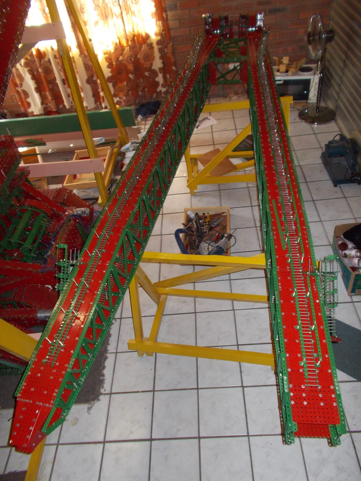
The crowd mechanism
I have also at the stage (January
2016) completed the double boom crowd mechanism – shown in Figure 13,
upside-down on trestles. The
large-toothed racks are visible. There were also cut by Steelcut Services with
great precision in 12½" sections.
The pinion drives are contained in the two boxes which can ride along
the booms on a total of thirty-two 1" diameter flanged wheels. On the prototype the booms are guided by
friction pads which can be adjusted for wear.
I decided to depart from this design feature in the Meccano model due to
the difficulty of creating such large units with no bolt heads in the way of
the friction pads. There are a total of
eight rails installed on which the flanged wheels ride. A first attempt at using Meccano-style parts
to create these rails was bedevilled by a lot of annoying clickety-clack so
instead I got my friendly hardware man to cut eight lengths of 32mm wide 1mm
gauge galvanised hoop iron, being careful to avoid getting any kinks. With appropriate mounting holes drilled these
work extremely well and the operation is smooth and almost noiseless
 |
| Fig 13: Twin crowd booms and slide supports |
Each of the two crowd drive guide
boxes will have a drive motor driving onto the toothed rack via a 28-tooth
pinion. The latter has a spring loaded slip clutch to ensure that no strain
will occur in the drive train should an inexperienced operator not cut the
crowd power in time. I am also
incorporating spring loaded override bumpers to prevent the boom crashing when
they come to the end of their travel in either direction, as there is a lot of
mass on the move in the digging part of the machine.
 |
| Fig 14: Hollow swing kingpin and 8 floor lift (elevator) shaft |
In figure 14 is shown the hollow
kingpin and its eight supporting bulkheads, looking rather like the guidance
vanes on a SAM missile! The Kingpin is octagonal, formed from 135 degree obtuse
girders with 2 ½ inch plate faces. Also shown in this figure is the 63 inch
long lift (elevator) shaft for the three-person lift which will run in the
hollow kingpin, described earlier. This will give about 57 inches of travel
needed to get from the lower works to the roof of the machinery hall, with a
stop for the digging operator halfway.
The steering arrangements
I have now (February 2016) started
work on the massively strong anchorage arms for the “hydraulic” steering
thrusters. These are fabricated from a
mixture of 2mm and 1mm gauge plate.
Because there is a non-standard angle involved I opted to ream 4 holes
in the 2mm plates out to 8mm and use M8 bolts instead of drilling multiple
non-standard position 4.2mm holes in order to get a strong join. This work is visible figures 15 and 16.
 |
| Fig 15: Steering thruster anchorage at one end (note 19mm spanners on floor) |
 |
| Fig 16: An overall view showing steering thruster anchorages at both ends |
Parallel with work on the
anchorages is the creation of the thrust units themselves. One of these is seen in Figure 17. At one end is a motor, its output pinion driving
a large toothed gear (27t). This gear is bolted to a 12t pinion which drives a
35t gear which is fixed directly onto a length of M12 threaded rod. This rod created the sideways thrust to swing
a pair of crawlers round by revolving in a large aluminium collar with an M12
thread, held in an aluminium fork piece which was machined from 70mm diameter
stock. These “half universals” are shown
in Figure 18 along with some 70mm aluminium faceplates which bolt onto the ends
of the steering tiller arms, which in turn are shown in Figure 19 (3 of
them). All of this allows the ram to
move with two angular degrees of freedom at the tiller arm (the fork pieces
revolve against the faceplates on M12 axles). The other end of the ram can also
move with 2 angular degrees of freedom. Examination of Figure 17 which shows
the ram motor and gear box reveals a very strongly built box behind the gear
box which can rotate with respect to the gear box through a small angle. This box in turn can rotate about a
perpendicular axis with respect to the anchorage arm, thus achieving full
movement in solid space.
 |
| Fig 17: Steering thruster motor, gear box and swivelling device |
 |
| Fig 18: Aluminium fork pieces and faceplates |
 |
| Fig 19: Rock and roll suspension devices with steering tillers and parts from Fig 18 |
All the above work will allow
steering action to take place no matter what height the jacking pistons have
been set at in the case of the prototype.
My model, which has a fixed position for the levelling pistons, still
needs these degrees of freedom due to the fact that the steering rams do not
swing in one horizontal plane.
March 2016:
Lower Works Righted
Figures 20 and 21 show the lower
works turned right side up and placed on a special set of wooden supports which
give support at the centres of the four straight sides. The four rock and roll supports for the
crawler system have also been bolted in place by passing the M20 bolts up
through the corner boxes of the lower works frame and putting M20 nuts in
place. This required using an hydraulic
car jack to life each corner so that the long bolts could be slid into place.
 |
| Fig. 20: Lower works righted. Note - steering thruster anchorages and rock and roll devices with steering tillers in place |
 |
| Fig. 21: Similar to Fig. 20 |
The support system has been
designed so that the 8 crawlers can be slipped into place on their horizontal
M20 rocker axles which go into the holes in the rock and roll devices without
further lifting. At that stage the crawlers will be about an inch above floor
level. When all crawlers are securely in
place the wooden structures will be dismantled in situ and the final one inch
journey to the floor will be made, aided by the car jack. The wooden supports have also been placed so
that they will not interfere with the crawlers in a lateral sense.
Also visible in Figures 20 and 21
are the now completed anchorage systems for the steering thrusters. These structures are very strong as they have
to withstand enough lateral thrust to swing the crawler pairs round under the
1200 Kg machine.
It will also be noticed that the
hollow swing kingpin has been bolted in place.
In Figure 22 one can see the temporary placement of the elevator
shaft. This shaft will eventually be fixed
to the machinery hall above and will rotate inside the kingpin. Personnel board the elevator at a station which
is level with the lower works underside and can alight just above the top of
the kingpin (to get to the digging controller’s cabin) or on the roof of the
machinery hall.
 |
| Fig. 22: Elevator shaft inside hollow swing kingpin |
The elevator shaft does not extend
to ground level as the machine was designed to have a height clearance of 16
feet between the crawler pairs so that the ground man could drive his bulldozer
back and forth through the alleyway thus created. This is enough clearance for a Caterpillar
D10 bulldozer, for example (a D10 on this scale would be about 10 inches high.
It was the largest production bulldozer available in 1973 when it was introduced).
May 2016:
The Crawler System
All eight crawler trucks have now
been assembled and all belts installed.
All sixteen gear boxes have been completed and tested for
adjustment. This is crucial as
clearances are about 1mm between the successive gear wheels in the reduction
sequences and there must not be any touch.
Each gearbox has been fitted with a slipping clutch so that there can be
some differentiation as the machine turns when steered. (Ideally there should also be some voltage
modulation taking the geometry of the trucks into account – feedback – but I
will need some advice on that one). The
parts of a slipping clutch are shown in Figure 23. There are two turned brass faceplates, 40mm
in diameter, a leather friction plate between and a 4kg compression
spring. This clutch is placed at the top
of the reduction cascade (fastest axle) so the torque available to the final
drives is very large.
 |
| Fig. 23: The
parts of a slipping clutch |
The crawler belts represent a great
deal of work, some of it rather tedious.
There is a total of 6 fishplates per crawler tread, four 2-hole ones and
two 3-hole ones. There are also 6 lock
nuttings per tread and a total of 40 fixers per tread. There are 368 treads altogether so that is
14,720 fixers and 2,208 fishplates.
The 8 crawlers are now all
installed on their M20 stainless steel rocker axles and secured in place by a
total of 16 turned collars. Figure 24
shows the installation of the last crawler about to happen (onto a M20 stub
axle protruding from the rock and roll suspension unit).
 |
| Fig. 24: Support
to final crawler truck |
Figures 25-27 show the Completed
installation of 8 crawler trucks from different angles.
 |
| Fig. 25 |
 |
| Fig. 26 |
 |
| Fig. 27 |
Figures 25-27 show the Completed
installation of 8 crawler trucks from different angles.
The lower works are still supported
by the wooden support structure in these pictures so the belts are hanging
slacked onto the ground. When the wooden
support is removed they will ride properly on the 8 positioning bottom rollers
on their sprung rocker axles. Belt
tension has been adjusted by means of the larger rollers at the top of each
unit also on sprung rockers.
Before lowering to the floor I will
do a final check of the motor polarities and will also tidy up the wires
bringing in power.
I will delay installation of the
steering thrusters as there is quite a lot of work to do on the underside and
the only way in is through the gap between crawlers. With the thrusters in place there will be
enough room to drive a scale caterpillar D10 through but then I’m not that
compact!
28th June 2016
Upper torroidal ring and machinery
hall floor pan
The upper rotating toroidal ring
has now been completed and rails have been installed on both upper and lower
rings. These rails were made from 40x3mm
mild steel flat. My friend Dixie
Westcott used his homemade plate roller to roll the rails into 105cm diameter
hoops. Suitable holes were then drilled
for mounting. The lower rail also needed
to have 165 eight mm holes drilled at a spacing of 21mm into which some 40mm M8
bolts were placed, with free ends facing outward. These became the teeth for the large swing
ring gear. Another plate rolled flat was
also made with 64 similar holes drilled and this would become the 64 wheel
roller race with 32mm brass flanged wheels installed on M8 bolts. These developments can be seen in Figures 28
and 29.
 |
| Fig 28: Torus, with 64 wheel race |
 |
| Fig 29: Lower rail |
The 4 swing motor/gearboxes have
also been installed and wired up. These
provide immense torque for swinging what will be the 700kg upper part of the
machine at a realistic speed. This work
can be seen in the following 2 photographs (Figures 30 and 31) taken by a
professional photographer, Clint Bradfield of FotoFirst, Grahamstown. I have decided to place the swing motor gear
boxes on the outside of the swing ring.
This is different from the prototype but I took this step for 2 reasons.
Firstly, I did not want to interfere with the frame of the upper toroidal ring,
thus reducing its strength and secondly, had these units been inside it would
become impossible to service them without dismantling much of the machine.
 |
| Fig 30 |
 |
| Fig 31 |
The upper swing bearing consisting
of 8 smaller brass flanged wheels fixed to the hollow swing kingpin which in
turn is fixed to the lower works can be seen in Figure 32. These wheels roll on a rail installed on the
inside of the upper toroidal frame.
\
 |
| Fig 32: Upper swing bearing |
The 6" deep upper torus is of
course part of the floor pan of the machinery hall and as such now needed to be
developed into the said floor pan. This
has been done by attaching outer bulkheads to 24 of the 32 outer girders of the
torus (the remaining 8 outer girders anchor the swing motor gearboxes). The result can be seen in Figure 33. Here we see that the floor pan is rectangular
on three sides (the front and sides) while the rear is a segment of a circle,
concentric with the kingpin. (There is also a slight bulge on the front)
\
 |
| Fig 33: Floor pan |
The rear end of the floor pan can
be seen to have 6 empty boxes. These
will house a total of 48 one litre concrete blocks with a total mass of about
125kgs. This is the counterbalance
weight needed to counter the overturn moment of the main boom, dipper arm,
crowd arm and stiff leg.
The plating of the hall rear end is
complicated as the lower part (below the colour change line) is in fact a
segment of a frustum of a cone. It is
not possible to plate this with rectangular plates without doing considerable
mutilation and landing up an untidy job.
I have therefore opted to cut and drill some custom shaped ones out of
scrap galvanised plate kindly provided by Mr Bud Hare, a local plumber. The lower 6 have been installed and the
effect is seen in Figure 34.
 |
| Fig 34: Curved frustum of cone |
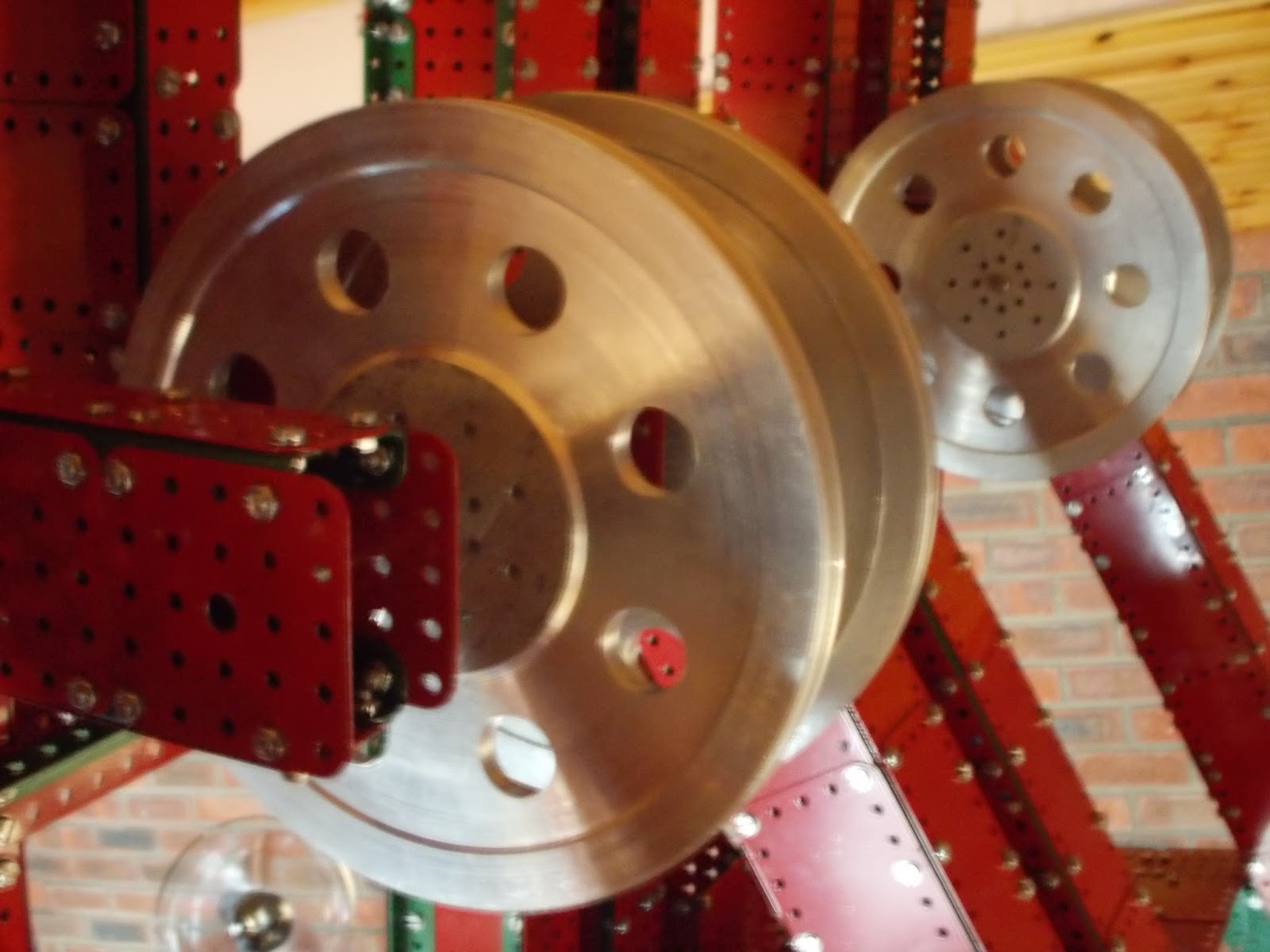
The next major task will be the
creation of the 2 double hoist winding drums driven by 4 motors. The prototype had 8 motors of 1000hp each but
4 window winders will be sufficient on the model, especially since I do not
plan to ever fill the 1½ cubic foot dipper with stone! The main gears of the hoists are these
beautifully made 12" ones cut by SteelCut Services – Figure 35. I could not resist the temptation of having
12 cut even though only 2 are needed.
With laser cutting the most expensive unit is the first as the cost of
design and storage in the machine’s CAD (computer aided design) system is
incorporated. Once the design is held
further copies are only slightly more expensive than the cost of the material.
 |
| Fig 35: 12 inch main gears (12 of) |
Other details are being filled in
along the way. One of the 2 electric
supply cable winding drums can be seen in Clint Bradfield’s pictures (Figures
30 and 31 above). The red rounded
structure to one side of the winder would house a slip ring capable of handling
the 14,000v three-phase incoming power at the rate of 22 megawatts on the
prototype. On the model these are just
for show as the actuating power will come in via 2 multicore cable harnesses,
one to the lower works and one to the upper works. (I do not plan to put a multidisc
slip ring between upper and lower works as there are too many individual cores
and should one lose contact the consequences could be serious with, for
example, 3 swing motors trying to drive a stalled swing motor).
17th July 2016
The winding drums and some corrections to the rear end
Work on the winding drums has
started and these can be seen mounted in Figure 36. On each side is a double drum with a central
divider so that the cables remain separate (4 cables altogether then). The drums have 6" faceplates at each end
and a 7½" divider. Each is fixed to
a 12" driving gear which will be driven directly by the output pinions
from 2 motors.
 |
| Fig 36,: Winding drums |
I also decided to change the rear
end of the machine slightly. I have added 7 bulkhead framers of width 3½"
each. These will be the frame to the
section of a frustum of a cone which is the lower part of the rear end. This step achieves two aims. One is that a slight scale error in the
machinery hall versus the lower works has been corrected. Secondly, the rear end
supports in the picture (Figure 37) support 4 motor-generator units (M-G) which
are very heavy in the prototype as they convert 22Mw of high voltage AC 3-phase
power into 440 and 220 volt DC. I shall build representations of these driven
by Meccano 6 volt motors so the extra framing is all to the good.
 |
| Fig 37: New rear frames |
Figure 38 shows the floor pan taken
from above. Compare the shape with the
actual 6360 floor plan shown in Figure 39.
 |
| Fig 38: Aerial view of floor pan |
 |
| Fig. 39: Diagram of floor pan |
Finally, the plating of the two
side extension “lugs”, 5½" outward has been effected using some purpose
made plates recycled from my plumber’s scrap heap (Figure 40) rather than
mutilate rectangular plates to achieve the rather complicated shape.
 |
| Fig 40: Bottom of the rear "side lugs" |
3rd September 2016
The double gantry
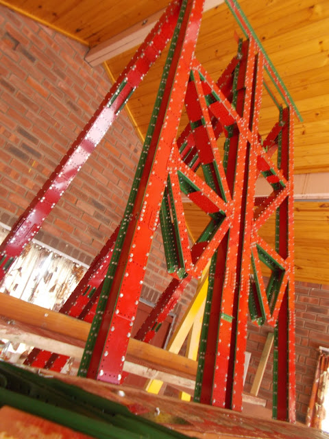
I have now started work on the next
main phase, the double gantry above the machinery hall floor, which supports
all the upper parts of the machine, viz., main boom, crowd arm and by way of
pinioned joints, part of the dipper and stiff leg.
 |
| Fig 41: 8 main uprights. Note scaffolding to work from. |
Figure 41 shows the eights main
struts in place. Each of these is a
closed box beam made from 2½" wide plates onto corner girders. The rear four have girders facing inward and
hence one plate face had to be fabricated entirely from 2½" x 2½"
plates since fingers cannot get inside to hold nuts 5½" away. The front four have girders facing outwards
and hence resemble two I-beams bolted side by side. This was necessitated by the fact that there
is a considerable amount of cross-bracing between the front uprights as well as
strong supports to the crowd drive mechanisms.
The outward facing girders were convenient to bolt all this on.
 |
| Fig 42: Some cross-bracing |
The start of the cross-bracing can
be seen in Figure 42. Strong corner
gussets have been installed with a high bolt density as can be seen in detail
in Figure 43. Plates of 1.0mm gauge have
been used for most of the gantry.
 |
| Fig 43: Corner gussets |
I have designed the gantry so that
the top four feet or so can be removed in order to get the model through the
garage door. Each upright member of the
gantry can be split in two at just above the hall roof line. This will require about 300 nuts to be
loosened. The break in the lower X-brace
can be seen in Figure 42. Only the upper
V part of the X has been assembled. The upper part of the gantry will have a
mass of about 100Kg and so by attaching two wooden lifting battens it should be
easily managed by four people.
2nd October
2016
The Stiff
Leg, Hoist, Pulleys, etc
The stiff
leg has now been fabricated and two views (front and back) are shown in Figures
44 and 45 respectively. This unit is
just over 6 feet long and is built from about 300 plates, most of which are 4½"x2½". Each of the two main stanchions is a closed box with
butt-joined girders in the corners and lap-joined 4½"x2½"
plates (0.6 gauge) spanning. The cross
join between these uses some 1.0 gauge plate as it must resist any torsional
stress applied. It is also a totally enclosed box. Visible at the upper end is a piece of 20mm aluminium
rod which will act as a hinge to the twin crowd boom and the dipper
handle.
 |
| Fig 44: Stiff leg, front view |
|
 |
| Fig 45: Stiff leg, rear view |
Further work has been done on the gantry. In Figure 46 some more bracing (in green) can
be seen. These braces are in planes
perpendicular to the main bracing.
As with the main bracing members these members can be split in two just
above the machinery hall roof so that the top half of the gantry can be removed
to exit the machine from garage.
 |
| Fig 46: Gantry bracing |
In Figure 47 four hoist pulleys at the gantry top are shown. These are mounted on very strong bearing
units and run on 8mm axles. Figure 48
shows the two bearing boxes for the crowd mechanisms. My crowd drives will rock on 8mm axles which
are offset from the drive axles (also 8mm) by 1". I did not want to let the weight of the crowd
boom rest on these drive axles (this weight is magnified when the crowd boom is
in the cantilevered full back position).
I am using two motors to drive the crowd through slipping clutches. Since ©Meccano does not utilise ball bearings
I was afraid that the drive shafts would experience too much clamping action if
things were done as on the prototype (bearings rocking on the drive
shafts). This change has also
necessitated a slight change in the geometry of the upper section of the
gantry, but the spirit of the machine will not be lost, I feel.
Among other things I have also spent some time manufacturing another five
hundred 5½"x2½" plates. Three hundred of these plates will be used in
the machinery hall roof. My original
plan was to use flexible plates here (cut from empty spray paint tins, coffee
tins, etc.). I have, however, rethought
this and realised that the roof needs to be stronger due to the strategy for
transport (removal of the upper part of the gantry).
 |
| Fig 47: Four 8 inch hoist pulleys |
 |
| Fig 48: Crowd drive rocker axles |
3rd December 2016 : Some
details, some gaps filled and the Dipper .
Some detail has now been installed.
Fig 49 shows the present state of the main hoist winding drum area. The drive
to these drums is supplied by four window
winder motors as explained before but now eight imitation representations of
the eight 1000 hp electric motors on the
prototype have been installed. These are seen to have six sided bodies (
employing some 110 degree and 135 degree obtuse angled parts) . On top of each
motor is a small aluminium fitting made from 20mm and 30mm stock, meant to represent the double impeller cooling
blowers for the 1000hp motors needed since the latter run almost continuously
and are too slow revving to run their own coolers. Also visible on each motor
is a lifting hook. I used M6 eye bolts as M4 were not available. A bit clumsy
but they give the idea.
 |
| Fig 49: Some detail in the winding drum area |
Also in evidence around this area is
a network of access platforms and stairs. As usual I use narrow strip for
horizontal rails and long bolts for upright stanchions. This theme is continued
in Fig 50 which shows some of the labyrinthine ladder network and servicing
platforms near the top of the gantries.
 |
| Fig 50 : Servicing platforms and access ladders on gantry |
In Fig 51 the large raised platform
at the very rear of the machine is now shown completed. This will support the
four large motor generator units , each consisting of a 14000V AC motor driving
four or six generators putting out 220
or 440 V DC
on the prototype. Below this platform are six large boxes which will house
about 125 kg ballast in the form of one litre concrete blocks .This is needed
to counter the overturn moment of the main boom and the three moving arms.
 |
| Fig 51 : Motor generator platform |
Work has also begun on the dipper. In
Fig 52 the handle to the dipper is shown. This is fabricated largely from 0.6
gauge plates overlapped with butt joined girders in the corners. The upper end
of the handle is narrowed down to 2.5 inches square by means of four purpose
cut plates. At this end an aluminium fork piece and collar can swivel. The 20mm
axle on which all three moving arms pivot passes through this collar. The lower
end of the handle is widened to 5.5 inches. This is where the digging bucket
will join on.
 |
| Fig 52 : Dipper handle |
The said bucket has been built too
and two views are shown in Figs 53 and 54. The first is from the front offside
and shows the digging teeth while the second is from the rear offside and shows
the two doors which open on hinges at the top to release the load. I still need
to install the locking latch system as well as a system to slow the closing of
the doors (nubbers). Then the components can be mated to complete the dipper
handle.
 |
| Fig 53 : Digger bucket front off-side view |
 |
| Fig 54 : Digger bucket rear off-side view |
It may be noticed that I have
coloured several parts which are traditionally green in red instead. I felt
that a uniform red for the main body of the bucket would be more pleasing to
the eye. This part of the bucket employs a double skin with about an inch
between in parts. This is done to give an idea of the massive steel casting
which was the prototype bucket front.
Readers familiar with the 6360 will
notice that my bucket has been modelled on the revised bucket seen on the
machine after it was taken over by Arch Minerals. The earlier bucket seen on
the machine in its time with South Western Illinois Coal Corp. was replaced by
this design which was easy to recognise by its distinctive side ribbing.
Perhaps the older bucket wore out? I would appreciate it if someone could tell
me the story.
2nd January 2017
Crowd arm, stiff leg, dipper and
motor-generator sets
The crowd arm and stiff leg have now
been installed with some help from two of my sons who were in town for
Christmas holidays. This is seen in Figures 55 and 56. Tolerances were quite
tight but nothing clashes and the motor drives can lift the units with ease.
The crowd drive motor/gearboxes are shown close up in Figure 57. The original
40mm slipping clutches have been replaced by 110mm ones,u as I felt the 40 mm
ones might not have sufficient pull. The solid brass face plates needed quite a
bit of cutting in the lathe as I had to start with a blank which was big enough
to grip securely in the chuck.
 |
| Fig 55: Proud arm and stiff leg now working |
 |
| Fig 56: Similar, from the front |
 |
| Fig 57: Close up of crowd drives |
Figure 58 shows the dipper, which has
now been put together, and the lifting hitch with four 8 inch aluminium pulleys
installed. This unit can only be installed once the main boom is in place since
most of its weight is borne by the main hoist winding drums through cables running
over another four pulleys at the top end of the said main boom.
 |
| Fig 58: Dipper with attached pulleys |
Figure 59 shows one of the four motor
generator (M-G) sets assembled. The roughly cubic structure in the centre
represents a high voltage motor (14000 volts three phase AC) which drives four generators
with open frames. Ersatz windings in the stators were made using three hole
strips and stacked washers while ersatz rotors were made using the tops of
Rustoleum spray paint cans cut, pushed together and sprayed black.
 |
| Fig 59: One of four motor generator units installed |
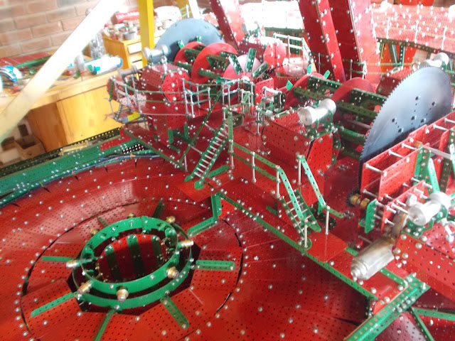
In Figure 60 all four M-G sets can be
seen installed on their raised platform at the rear of the machinery hall.
Although these are cosmetic in the sense that they do not form part of the
model’s power train, they all do actually revolve. The H.T. motors in the front
two actually have motors inside driving through speed step up boxes (since the
output pinions revolve too slowly) which drive the four larger open cage
generators as well as the parallel sets with six smaller fully enclosed
generators by means of Meccano sprockets and chain. (One of the few Binns Road parts
used!)
 |
| Fig 60: Four motor generator units installed |
The axle common to each M-G has been
journalled in only four points due to inevitable alignment problems. On either
side of every H.T. motor are flexible drive units to avoid these problems.
These flexidrives were made from a central 3mm thick disk of insertion rubber
and turned brass bush wheels on either side with bolts between as shown in an
exploded view in Figure 61. I got this idea from a flexidrive unit in the prop
shaft of a rear wheel drive Fiat motor car I once owned.
 |
| Fig 61: Parts of a flexidrive unit |
An aerial view of the M-G sets is
shown in Figure 62. Compare this with the floor plan of the prototype shown in
Figure 39. The M-G layout was quite time consuming to build as many parts
needed to be specially made. These included 44 bush wheels for flexidrives as
well as for the frames of the open generators. Although most of the plates used
were made from recycled coffee tins and spray paint cans, the whole structure
is quite heavy. This is all to the good as it acts as a counterbalance. On the
prototype the counterbalance effect was even greater as these were very heavy
items. Once the enclosed cabin of the machinery hall is under way I will have
to install some very substantial travelling cranes to enable these units to be
lifted out for service etc.
 |
| Fig 62: Aerial view focused on rear of floorpan |
Work on the main boom has now been
started in another room. This will weigh about 80 kg but I am hoping to
minimise the need for help to get it into place at an upward angle of 45
degrees in the same way as the builders of the prototype got the boom up. I
shall install two smaller pulleys at the upper end of the boom and build a
special highly geared down double winding drum to pull it up. I cannot use the
hoist drums as they revolve quite fast and do not have the pull for this job. (The
hoist process would be tedious to watch if it happens too slowly. Hoist and
crowd speeds need to be matched for ease of operation too.)
1st
March 2017
Main boom
During
the past 60 days substantial work has been done on the 12 foot 8 inch long
,6000 nuts and bolts main boom. The two halves were assembled in the study of
my home and then taken up to the garage which is the Marion assembly site where they have been
joined together and a lot of detail filled in. I have provided the best
pictures I could get but this has been difficult due to the fact that the unit
almost completely fills the space cleared in front of the model so far. Figures
63, 64 and 65 are the best overall views my wife Eileen could get. (She being a
better photographer)
 |
| Fig. 63 |
 |
| Fig. 64 |
 |
| Fig. 65 |
|
|
Figure 66 shows a tapered lower end
at one side. This was assembled from some specially prepared 1.0mm plates with
a bend just off diagonal which are shown in figure 67. I decided that this was
the neatest way of creating the tapered end keeping the look close to prototype
while maintaining great strength.
 |
| Fig. 66: One tapered lower end |
 |
| Fig 67. : Four 1.0mm plates with an off-diagonal bend each |
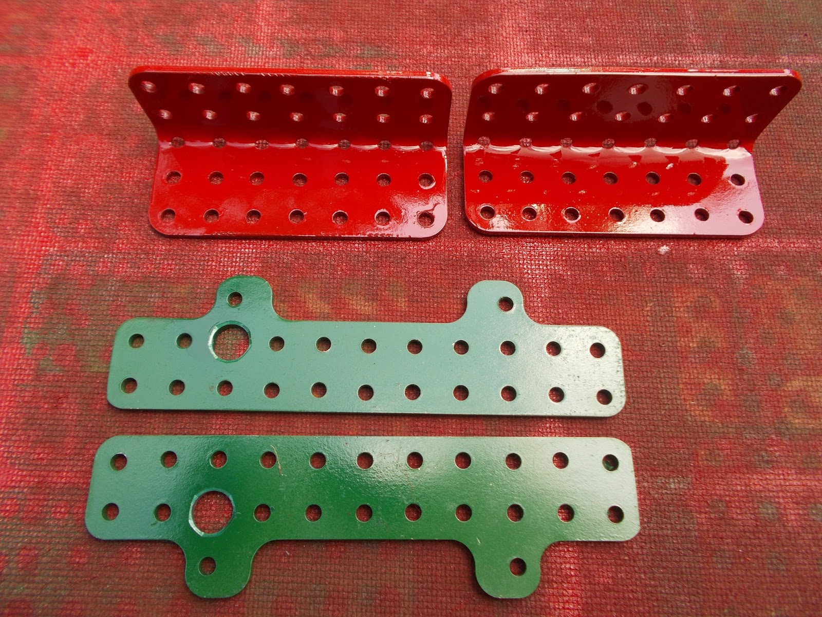
In figure 68 are shown some strong
angle brackets made by bending 3.5 by 2.5 inch 2.0mm plate. These will be
bolted onto the 2.0mm plate between the angled bent plates in figure 66. Also
seen in figure 68 are two hinge parts (green) with 10mm holes . Their gauge is
3mm and the will bolt onto the red angle brackets and form one half of the
hinge supporting the main boom . An M10 bolt will serve as a pin.
 |
| Fig. 68: Two angle brackets and two hinge plates |
Figure 69 is a view of the bearing
box for the four 8inch aluminium main hoist pulleys. Figure 70 is another view
of this unit with details of some access stairs visible I am indebted to
Classic Construction Models and photographs of their highly detailed brass
model of the 6360 for information on these finer details.
Also visible in figure 69 is a turned
aluminium 4 inch pulley mounted in a swinging yoke and running in a plane which
stays perpendicular to the plane of the main hoist pulleys. This is the first
of four such pulleys . I plan to hoist
the main boom up into position using a strong motor driven winding drum and
another four sheaf pulley system .This is the way the boom was installed on the
prototype. I calculate that tension in the cord should only be about 12kg,
which is manageable.
 |
| Fig, 69: Bearing box for hoist pulleys |
 |
| Fig. 70: Similar, showing access ladders |
In figure 71 is shown a transfer
stairway between two main stairways going up one side of the boom. I’m not sure
why it was necessary to have four different routes for staff to get to the top
of the main boom. Perhaps someone in the know could enlighten me?
 |
| Fig. 71: Transfer ladder between upper and lower main stairways |
Finally figure 72 shows some cosmetic
work at the front end of the bearing box. The strength of my version really
lies in eight parallel bulkheads with cross bracing bulkheads between .Three
different stresses have to be designed for: (1) The 8 inch load hoist pulleys
(2) The 4 inch boom hoisting pulleys. (3) The twelve stay rods which will
connect the top of the main boom to the top of the gantry.
 |
| Fig. 72: Cosmetic work at front of bearing box |
8th May 2017
Machinery hall enclosure and auxiliary equipment
Considerable progress has now been
made on the walls and roof of the machinery hall. In figure 73 two of the eight
roof trusses are shown. In figure 74 seven of these trusses have been installed
atop stanchions each made from two girders and one flat girder in cross
section. In this picture one can also see considerable side cladding installed.
I am quite pleased with the effect of the two colour parts. In order to give a
sense of the prototype machine’s colour change about 40% of the way up the
sides I have painted a series of plates green on one side and red on the other.
These have used on the upper part of the walls, green facing out and red facing
inwards. This results in the inside being uniformly red.The prototype had a
series of crossed stay rods installed to stiffen the outer wall panels. I am
using green narrow strips highlighted against the red plates to show this. I
used Pythagorus’ theorem to fit these. For example 8 ,15 and 17 are integer
sides of a right angled triangle, so many 18 hole narrow strips had to be cut.
Since all my stock parts are 25 holes long, I landed up with a large pile of 7
hole narrow strips which were absorbed elsewhere.
 |
| Fig. 73: Two roof trusses |
 |
| Fig. 74: Machinery hall from the rear |
 |
| Fig. 75: Frontal view |
Figures 75 and 76 show frontal views
of the hall. It took a lot of planning to get the look of the front right. The
two outer front gantry main supports had to protrude from the hall at just the
right place. Also the central “tepee” shaped projection needed many plates to
be cut and drilled. The stiff leg pulls up into an almost vertical position on
either side of this projection.
 |
| Fig 76: Close up of projection between stiff leg struts |
Figure 77 shows the beginning of the
roof cladding. This is being done with green painted 5.5 by 2.5 ( 0.6mm gauge)
inch plates. Since all cladding plates of the hall are this gauge and the
stanchions are all channel beams as explained, the structure is turning out to
be vey strong. This is rather like a motor car with a chassis as well as a
monocoque body shell. (This reminds me of a picture I have of a 1980’s Rolls
Royce being built.)
 |
| Fig 77 : Start of roof cladding |
Figure 78 shows the
lift (elevator) shaft now in place. The hoist mechanism of this elevator is
seen at the top of the shaft in figure 79. The roof will be the upper stop for
the 3-man elevator while in figure 80 the midway stop on the machinery hall
floor is shown.
 |
| Fig 78 : Elevator shaft |
 |
| Fig 79: Elevator and its mechanism |
 |
| Fig 80 : Midway station on elevator |
Another feature I am working on at
the moment is the set of four travelling gantry cranes whose purpose is to lift
out any motor etc. which may need repair. I have tried to get pictures or information
on these cranes but no one seems to be able to help me so I have had to use
some imagination in designing them. I believe all of four are necessary since
firstly, cranes can’t pass through the rear four main gantry supports. Secondly
a single crane at the front can’t pass through the elevator shaft and thirdly a
single crane at the rear would have an excessively long span (the same would
hold for a single crane in the front part of the hall.)
All the rails for the cranes have
been placed and work on one of them is shown in figure 81. To create smooth
running one piece rails I bought a 10 metre roll of 25mm wide hoop iron and cut
and drilled suitable lengths. The same tactic has been used on the rails for
the cross-travellers on the cranes. This will also ensure that the system is
not prone to derailments due to rail misalignment. I used the entire 10 metre
roll on the job.
Each crane has four actuations. The
movement of the cross traveller is performed by means of a 6 volt plastic motor
and a double sided winding drum ( which pays out cord on one side and draws in
cord on the other side.) Hoist is performed with the same kind of motor driving
an ordinary winding drum. The longitudinal motion of the cranes is performed
using one window winder 12volt motor driving two double sided drums to move the
two rear cranes simultaneously and the same arrangement moving the front two
cranes. The reason for this is essentially that I was unable to obtain enough
Binns road type motors and the window winders are too cumbersome and too
powerful to have separate ones for each crane. There is a fourth movement which
I have not tried to power with servo motors due to the lack of such but have
left it as a manual operation. In order for the cranes to be able to reach all
motors, etc., the hoisting hooks have been placed at the end of swivelling
cantilevered booms. Figure 82 shows some aluminium parts which I turned for the
swivel action as well as some 30mm V-pulleys and a special part I designed to
allow cords to be anchored using grub screws instead of tying knots. This is a
boon on the double sided drums where knots would be very tedious.
 |
| Fig 81: A crane from above |
 |
| Fig 82 : Various crane turned parts |
Figure 83 shows a motor gearbox
combination to move rear cranes longitudinally. A slipping clutch is
incorporated to prevent overwinding and snapping cords.
 |
| Fig 83 : Motor drive to both rear cranes |
Finally some cosmetic work is shown
in figure 84. These are the eight 625 hp swing motors made from Rustoleum paint
cans cut up and each fitted with a cooling blower made from aluminium stock as
before.
 |
| Ro |
2nd July 2017
Machinery Hall and Auxiliary
Equipment
Over the last two months the roof has
been completed. Figures 85 and 86 show this development. The four large
rectangular openings at the rear are for four of the six large ventilation fans.
 |
| Fig. 85: Roof cladding |
 |
| Fig 86: Another view of roof cladding |
The four overhead gantry cranes have
now also been completed and installed. Figure 87 shows a view into the rear at
this stage. The mechanism at the centre is a window winder motor and reduction
gearing, as well as a spring loaded slipping clutch. The output from this
gearbox (topmost shaft) is taken to two double sided winding drums via drive shafts
which incorporate two flexidrives each. (These have been described earlier) The
double winding drums pay out cord on one side and draw it in on the other, as
explained earlier, in order to move the gantry cranes longitudinally. This all
required several V-pulleys to route the cords correctly. The motion is smooth
and very quiet and the two cranes seem to move as one unit.
 |
| Fig. 87: Rearmost two cranes. Note common longitudinal drive mechanism near ceiling |
Focussing on the cranes themselves shows
a Meccano 6V motor fixed to the side of each. These drive through some Meccano
gears and power a double-sided winding drum again which in this case moves the
cross-traveller from side to side. Slung below each of the cross-travellers is
a short cantilevered arm which can rotate to reach all machinery on the M-G
deck. In each of these arms is a second 6V motor which drives a winding drum
controlling the hoist hook. In the picture the forward /reverse switches are
seen still attached to the motors. Presently these will be cut off and
repositioned in an auxiliary equipment control board just inside an opening to
the hall.
In figure 88 a close up of one of the
cranes is seen. The swivelling cantilevered arm is clearly visible but the
hoist hooks still need to be installed. The whole of the crane system described
so far at the rear is repeated at the front. Figure 89 shows a view of the
latter. Building the crane system was quite time consuming as I had to stop to
turn about 160 brass units, including 64 flanged wheels based on Meccano ¾ inch
ones but with wider flanges. Many bush wheels , V-pulleys and winding drum
parts also had to be made.
 |
| Fig. 88: Left rear crane detail |
 |
| Fig. 89: Front cranes |
Figure 90 is a view through the as
yet open sides of the machine. These openings will eventually be filled with
more plates (40%) and with a sheet of 2mm Perspex. The latter will allow the
winding drum area to be viewed under a bright light.
 |
| Fig. 90: View through open sides |
Figure 91 shows some work on the rear
cladding. The ballast boxes will be closed by panels made of 5.5 by 2.5 inch
plates with some of the holes reamed out to 7mm. I call these parts universal
slippage parts and the replace the slotted parts of Meccano. They allow
slippage adjustment in two directions. This slippage allows the lower rear,
which is a section of a frustum of a cone, to be covered. Two of the ballast
box covers are seen in figure 91. (Red parts). A green panel is seen above the
red ones. This is covered by ordinary plates (without slippage) as the area is
just a section of a right circular cylinder, which is much easier. There are
six panels in this upper region. Two will be clad in steel and the remaining
four in 2mm Perspex to allow viewing of the M-G floor and the service cranes.
The Perspex plates will be easily
removable by loosening nuts in the perimeter.
 |
| Fig. 91: Some rear cladding. Cylindrical (green). Frustum segment (red) |
Figure 92 shows a
very robust winding drum driven by two geared down window winders. This will be
temporarily mounted at the very top of the gantry to pull the 100kg main boom
up into position. Also seen in this figure is a cluster of four 4 inch
aluminium pulleys which will allow ten falls of 2mm braided steel wire when the
five similar pulleys at the top of the main boom are brought into play. Tension
in the wire will be about 12kg so that component will have a high factor of
safety but the pull on the whole cluster will be 120kg so it needs a strong
mounting.
 |
| Fig. 92: Winding drum and pulley sheaves |
 |
| Fig. 93: Lower works, left |
Before I rebuild the wooden scaffold
to work at the top of the gantry I have taken time to complete some detail with
regard to the access stairs and gangways on the lower works. Figure 93 shows
these at the left. The small green box in the centre will house some ½ inch
pulleys on which a retractable ladder will run. Figure 94 shows the right hand
side while figure 95 shows access to service the bearings of the large cable
winder.
 |
| Fig. 94: Lower works, right |
 |
| Fig. 95: Service access to front cable winder |
For Figures 85-90 inclusive I am indebted to Ms Lynette Rudman.
25th August 2017
Small Things, Big Things.
During the last two months or so I
have done some cosmetic work as well as some heavy lifting. In figure 96 is
shown the lower stop for the three man elevator which travels upward through
the hollow swing kingpin, its shaft being fixed into the upper works. Of course
this had to be circular, since the door of the elevator could land up facing any
direction, depending on the relative orientations of upper and lower works.
There are also two gangways going sideways to the stairs on either side of the
lower works.
 |
| Fig. 96: Lower works stop for elevator |
After attaching the above device to
the underside of the lower works I was finished with jobs which required me to
get bodily between the crawlers (quite a squeeze!) Hence I could now fit the
four steering thrusters into place. Two of these are seen in figure 97.
 |
| Fig. 97: Two steering thrust mechanisms |
Figure 98 shows the dipper swinging
from the 20mm aluminium rod which is also the hinge pin between the crowd arm
and the stiff leg.
 |
| Fig. 98: Dipper installed |
At this stage the scaffold has been
rebuilt but now raised to 7 feet above ground. This was done to allow
attachment of the temporary winding drum to the very top of the gantry. The
four pulley cluster in its swinging yoke has been securely attached the latter
and the whole device bolted to a strong oak timber frame which in turn has been
bolted to the cross beam at the top of the gantry using M8 bolts , in
preparation for hoisting the main boom into its position at 45 degrees to the
horizontal.
Figure 99 shows the latter in position.
 |
| Fig. 99: Boom hoist winding drum |
Some missing work at the top end of
the main boom has now been completed. Two large plates spanning the space
between the two arms of the main boom have been installed, one above and one
below. These were purpose made, cut from an old electric stove I scrapped some
years ago. (Some bits of the same stove were used in the Krupp 288.) I decided
that purpose cut plates would look neater than mutilated rectangular standard
ones, due to the strange angles and shape. Figure 100 shows this work as well
as twelve turned aluminium ferrules to receive the twelve M6 threaded rods I am
using to represent the twelve support cables which hold the main boom to the
gantry top. A matching set of ferrules is being installed on the front four
uprights of the gantry. The boom top ferrules have central tapped M6 holes
whiles the gantry top ones have plain 6mm holes. This is so that the final
length of the rods can be adjusted by turning them, rather like a one sided
turnbuckle.
 |
| Fig. 100: Completed top end of main boom |
Also seen in figure 100 are five 4
inch aluminium V-pulleys arranged in three swinging yokes. There are four
pulleys on the prototype but I installed an extra one to get two more falls of
cable thereby increasing the mechanical advantage to 10 so as to reduce the
tension in the cable. Some more access stairs are also seen in figure 100.
Once
again I am indebted to CCM (Classic Construction Models) of the USA
for pictures of their finely detailed all brass model of the 6360 for views of
such fine detail.
With the dipper now in place there is
quite a large forward toppling moment present and so I have started to install
some of the counterbalance weight consisting of 48 one litre concrete blocks.
Figure 101 shows 36 of these blocks covered with acrylic roof waterproofing and
mesh so as to avoid crumbling of the edges. I do not want any concrete crumbs
going into lower works gearboxes.
 |
| Fig. 101: Thirty-six ballast blocks |
With the steering thrusters now in
place the machine could be driven backwards so that its curved rear is one inch
away from the garage wall. During this operation the scaffold had to be
partially dismantled and rebuilt. The reason for the move is to give me enough
room to attach the main boom in the horizontal position. The machine is also
swung to give optimum room here.
With this done my wife Eileen, son
Andrew and myself were able to carry the main boom over and attach it to
waiting lugs using M10 bolts. The result is seen in figure 102.
 |
| Fig. 102: Main boom now attached, in horizontal position |
At this stage I
decided to replace the fabricated 4 ½ inch diameter drum in the boom hoist with
a smaller 40mm aluminium one. This will pull cable at one third the speed but
with three times the force. This new drum is seen in figure 103 as well as the
cable which has now been wound around the whole pulley system.
 |
| Fig. 103: New (smaller) aluminium drum for boom hoist |
Some smaller details include the
digging operator’s cab shown in figure 104 (note his chair and two control
levers which emphasise just how gigantic the prototype was) and the cable
winding mechanism for door release in figure 105 with an aluminium double drum.
Glancing holes have been drilled in it to anchor cables, with perpendicular
tapped holes to anchor same.
 |
| Fig. 104: Digging operator's cab |
 |
| Fig. 105: Small winding drum for door release cables |
One large operation that has now been
successfully performed is the hoisting of the main boom into its final position
at 45 degrees to the horizontal .The winding drum performed without fault. I
used a 12volt battery charger to power the motors and noted that the amperage
drawn did not rise seriously, so that one could conclude that the motors were
not under strain. I had expected that the frame of the machine would complain a
bit when a large forward moment was first imposed on it but there was no such
complaint. There was no creaking of the structure at all and so I am confident
that gantry and floorpan are adequately engineered.
During the lift I had to swing the machine
into the forward position once the end of the boom had cleared my roll up
garage door. The extra 200 plus kg added today did not bother the mechanism.
(The boom weight is about 100kg and I also loaded up over a hundred kg of
counterweight ballast.)
Figure 106 shows the machine with boom installed. The boom is now supported by six of the
twelve threaded rods planned. This is more than adequate support as the system
has a huge factor of safety built in. The only reason I am installing twelve
rods is to get the look of the machine right. I will install the remaining six
when I no longer have to work on the front of the gantry as these make walking
across the front impossible. The turnbuckle length adjustment was also very
easy to use.
 |
| Fig. 106: Main boom up at 45 degrees |
4th October
Completion
With the main boom now in place the
model could now be brought to completion. Clint Bradfield , a professional
photographer trading as FotoFirst of Grahamstown has now taken the following
high quality pictures.
The four hoist cables have been
connected up so that the dipper can be raised as can be seen in figure 107. The
trip cables to the door latches on the two bucket doors have also been
installed, as shown in figure 108. The cables run over two sets of small
pulleys back to the double winding drum shown earlier.
 |
| Fig. 107: Model completed |
 |
| Fig. 108: Digging bucket, showing twin door latches |
Another “model within a model” has
been installed at the very top of the gantry. This is a service crane which can
traverse the full width of the gantry. Figure 109 shows this area. For the
rails on which the crane runs I used more galvanised hoop iron so as to get
smooth travel again.
 |
| Fig. 109: Rear view of gantry top |
 |
| Fig 110: Service crane atop gantry |
The crane itself can be seen in figure110. There are
twelve ½ inch flanged wheels riding on the top of the rails and eight riding on
the bottom of the rail to prevent toppling
of the crane when lifting something heavy. It took a lot of fettling and
adjustment to get the crane to travel without bolt head clash but traversal is
now very smooth all the way across. The crane slews on a race which is a pair
of 50mm diameter aluminium face plates running face to face with some grease
between. (These plates have countersunk bolts to attach them to the upper and
lower parts of the crane and allow them to rotate without bolt clash.) I did
not build a wheeled race here as scale would dictate parts smaller than those
available in Meccano. A 3½ inch ring gear is attached to the upper face plate
to drive slewing, however (a
Binns Road part!). Traversal is performed by a
small double sided winch again, as described earlier. Hoist is via another
winding drum. These motorisations remain motorless at the moment as I have not
been able to source enough of the Meccano 6v motors. Once I get these fitting
them will be a quick job. The worst part will be rebuilding the scaffold to get
up there!
 |
| Fig. 111: Inside machinery hall, showing winding drums and motor generators |
A total of 10 Perspex viewing portals
have been attached to the sides and rear now so that the inside of the
machinery hall can be viewed. Figure 111 was taken with one of the panels
removed. This shows the main winding drums clearly. I am grateful to Deon of
Superior Signs Grahamstown for cutting all the Perspex sheets very accurately.
Five small Perspex sheets have also been fitted to represent the armoured glass
windows of the operator’s cab.
 |
| Fig. 112: Rear view showing roof top ventilators |
Finally, the six large
ventilating/cooling fans have been fitted to the roof, as shown in figure 112.
Except for a few 0.6mm plates in key positions( including the 3 ½ inch radius
quadrant plates) these have been built entirely from flexible plate recycled
from empty coffee tins and spray paint cans.
The amount of traffic through our
house to view the models is small as we live in a rural town and I feel that they should be
exposed to a wider audience. Hence I have decided to donate the model to anyone who
has the space to display it and the throughput of visitors to justify having
it. It could be a great crowd puller for somebody. I do not ask for any payment
to myself but would expect the recipient to make an appropriate donation to an organisation which
gives medical and other humanitarian aid to victims of disasters and conflict
worldwide. This is called The Gift of The Givers. My Krupp 288 model is also on offer on the same terms.
My contact details are:
Graham Shepherd
15 Ilchester Road
Grahamstown 6130
South Africa
27(0)46-636-1737
-----------------------------------------------------------------------------------------------------------------------------


Great model, looking forward to seeing more of it. You must have a huge collection of Meccano.
ReplyDeleteThanks, Stuart!
ReplyDelete(I make the part myself)
I have just added an update - 2nd Jan - have a look
regards
Graham
Hello, This blog is too informative and the pictures are giving a good decsription about Industrial Man Cooler Blower 18 to 48 inches. Thank you
ReplyDeleteThis site has lots of advantage.I found many interesting things from this site. It helps me in many ways.Thanks for posting this again.
ReplyDeleteRough Terrain Crane
It proved to be Very helpful to me and I am sure to all the commentators here! man and material hoist
ReplyDelete